VFX Assistant Technical Director
What I did for each shot in my showreel:
Shot 1) Glass Crack Fx
Shot 2) Glass Crack Fx
Shot 3) Glass Crack Fx
shot 4) Glass Crack Fx
Shot 5) Glass breaking and pole breaking animation
Shot 6) Drone Thruster
Shot 7) Drone Thrusters and bullet hits.
Shot 8) Drone Thrusters
Shot 9) Glass Cracking
Shot 10) All elements
Shot 11) all elements
Shot 12) Screen recording was all done by me
Shot 13) Screen recording was all done by me
Unfortunately Due to the lockdown and the epidemic the shows I worked on that were meant to come out by June 2020 have been delayed until next year. I am unable to say what I have done as it does go against my NDA. All I can say is that they were particle and smoke simulations. These shots would’ve played a huge part in my showreel as they were my best work so far but unfortunately I am unable to use them.
Fast and Furious 9 (Delayed)
Bramastra (Delayed)
All of the work has been done and written by me in this blog.
The pipeline
What is a VFX Pipeline
a pipeline is a simple way of talking about the various stages of making vissual effects in a movie. each role is effected by one and other, For instance. If modeling is not doing their job correctly then texturing, rigging and animating would not be able to do their jobs properly. It is important for each stage of VFX to get things right and a big part of them getting it right is by knowing each others roles and communicating with who they need to. This is why it is important for a VFX artists to know each stage of the pipeline.
Pipeline Roles
Concept: Concept artists are used to give an idea of what the show could look like. They do 2D and 3D sketching, sculpting.
Concept work would be forwarded to the director and producers to get approval so it can then be passed on to artists for possible referencing.
Software:
-Photoshop
-Zbrush

Matte Painting: Matte Painters are responsible for creating high quality digital painting. They tend to be used for backgrounds.
Matte painting would be passed on to comp after approval for the final image.
Software:
-Photoshop
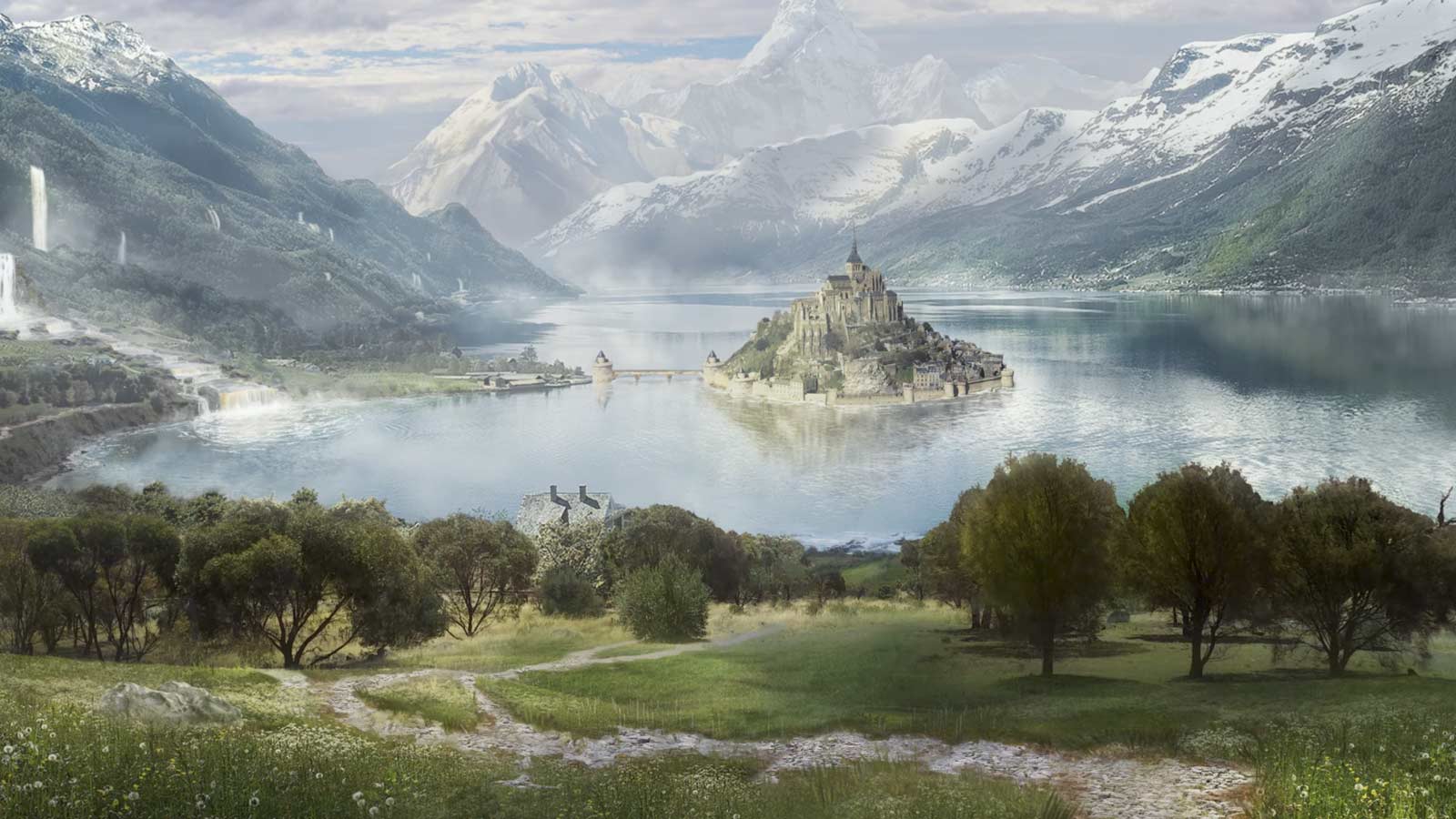
The difference between matte paintings and concept art is that matte painting are used in actual shots and concept art is used to show how the shot could look like.
Shoot: shoot take care of the on set photos which are used for references and for HDRI’s. They also use lidar scanning for digital assets.
Lidar scans would then be given to layout for camera mapping and to maybe even effects for scaling and digital assets. Set photos would be passed around to different artists for referencing, depending on the type of show it is and the stitched images for HDRI’s would be given to lighting for accurate lighting and possibly reflections.
Software:
-Jigsaw.
-Stig.

This image chows what Lidar scans looks like before converting them into polygons
Modeling: Modelers are used to create 3D assets.
The models would then be moved on to a variety of different artists for texturing, groom, rigging and animating. As designs change these would constantly be updating.
Software:
-Maya
-Zbrush
Rigging: Riggers are used to create the joints and controls of a assets such as people, animals, vehicles, etc.
Rigging would then end up with animation for movement but could be brought back to modeling (for bones) and creature (for muscles) if those are needed.
software:
-Maya
-Houdini

Texturing: Texturers are used to create the material and colour of the assets. They use texture map images on shaders.
Texturing would be given to lighting as modeling, rigging and animating is all done at the same time as texturing so it would skip straight to lighting so they can have a rough estimate of how the final image would look like.
Software:
-Substance Painter
-Mari
-Photoshop
-Maya
-Arnold
-Houdini
Matchmove: Matchmovers make digital cameras in 3D software. They also do mapping and tracking with markers.
Matchmove can be passed onto animation or FX depending on what the show needs as they are the main departments that need accurate scaling and virtual camera to match the backplates
software:
-Nuke
-Maya
-PFtrack

Layout: Layout use reference and lidar scans from shoot to determine where the virtual cameras will be and place the character .
Layout can be passed onto Fx and comp as comp would need it for the tracking markers and Fx would need it for the position and scaling.
software:
-Maya
-PFtrack
Animation: animators are used to create the movement of a character. They use the controls from riggers and then cache out their animation.
Animation would be then given to creature and FX. Creature artists would use animation for muscles and for hair / fur dynamics if they are needed and FX would need them for certain effects if the animation needs those such as, car on fire, thrusters from jet, missiles, magic from hands, etc.
software:
-Maya
Creature: creature atrists are used to create the realistic look for character. They deal with hair / fur, rigging, hair / fur dynamics, muscles, muscle dynamics.
creature work would be passed back and fourth with rigging and animation as it depends on the type of issues people have but other than that it would go to texturing or even lighting for the final image.
software:
-Houdini
-Maya
FX: effects artists create simulations in 3D software. They deal with fluids , smoke, fire, debris, vehicles crashes, explosions, magic, etc.
FX work would go straight to lighting for the final renders. depending on the show sometimes you will have to update certain geo you have used from animation or layout.
software:
-Houdini
-Nuke

Lighting: lighters are used to create lights for virtual scenes. Their job is to match the light to the live action plate.
software:
-Maya
-Nuke
Roto: Roto artists are used to create mattes for certain objects which are usually moving.
roto work would be given to comp for the final renders.
software:
-Noodle
-Nuke

Comp: A compositor is responsible for the quality of the final images. They are used to combine a layer of finalised material to create a balanced look.
comp is the final stage for a vfx shot. Once comp is done it is usual published and given to the client.
-Nuke
Editorial: The vfx editor is responsible for overseeing all of the visual effects in the production. They go over every shot that comes out of the production and look into any missing fine detail. If there is a problem they should always be creative enough to think of solutions.
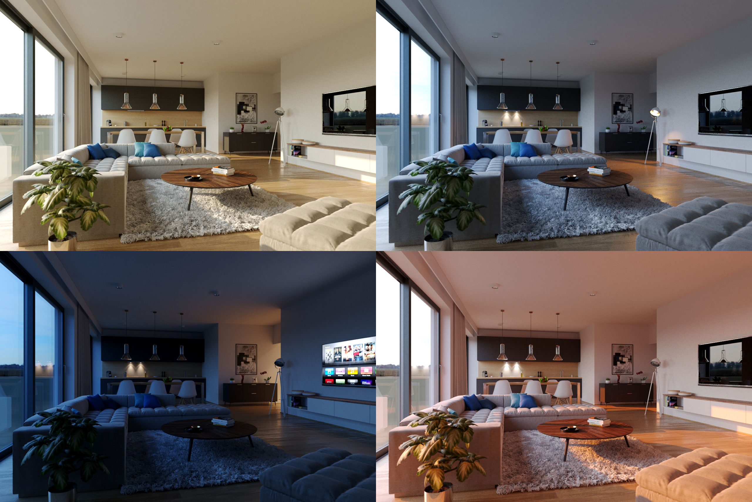
Grading: Graders make sure to improve the image for presenting to the clients. They deal with colour correction, contrast, saturation. They must have a really good eye for detail in terms of blending in colours and changing them to what the client wants.
Software:
-Nuke
In order for the show to finish on time, all of the departments need to run at the same time so asset packages keep on updating. The way asset packages work is once someones work is approved such as animation it can then be imported using the companies asset package plug in for the software for FX. These assets are always being reviews through dailies so that we know what to improve on and how to retain the industry standard level of work. The company mainly uses image sequences for dailies and client reviews. Sometimes if it’s really early stages or if the farms are full / have issues then we would use playblasts. Asset packages are only used once they are approved.
My role in the pipeline:
For my role as a Fx TD my job is to create effects set-ups for artist to use like a tool to add to the geometry needed and to create variations such as smoke, fire, particles, destruction, etc. My role fits in the Fx department in which my main software for use would be Houdini. Once everything is rendered, in order to add my Fx together and to change the AOV’s, I would switch to nuke. Fx is in the middle of the processing in VFX as anim, layout, environment, rigging, etc. all effect the outcome of Fx as sometimes the models might change which means maybe anim might change so the effects would not be in the right place meaning that caches and updating assets packaging would need to be done. A lot of the time Fx TD’s would spend recaching shots due to the constant tweaks in anim and modeling. This reduces the degrading of source material.
Pipeline at DNEG:
Working at a huge company, there are a lot of things that make sure the shots are in the correct place, shots are assigned to the right person, correct renders / shots are approved. At DNEG we use a API called shotgun which allows the coordinators to assign artists shots which can be creating from scratch or picking up other peoples work. We link the data to a internal software that we use to locate shot files from renders. For instance each render / cache has a file location which you can then pick-up by copying the render link either for Maya, Houdini, Nuke, etc. And pasting it into the software that you are using or paste it into the terminal. The software also allows the artist to see who the artist of the render was and when it was rendered. We also use it to publish to dailies, approve the work and collect work from any department. This system is used in smaller companies too in which i used Shotgun to access internal data from a external source when i was working as a look developer at LipSyncPost. For delivery at DNEG our outputs formats are always EXR’s as they allow you to export AOV which are later on used to customise / change in compositing. In Fx we still change AOV’s in Nuke to make our effects look nicer for dailies. This allows us to retain the quality of the source material.
Talk with Alan Woods
Alan Woods came in from Framestore to talk to us about how working as a CG and VFX supervisor is and how he got there. He also spoke about how bidding works in Framestore and their amazing new project they have been working on.
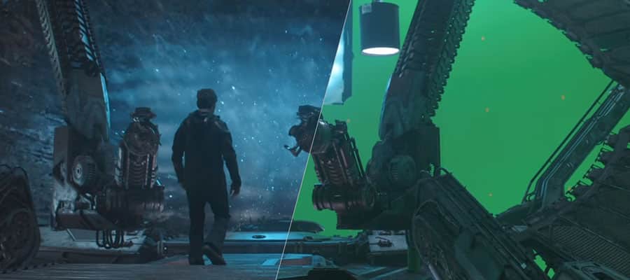
Alan taught me so much about the industry that I didn’t know about such as being a supervisor requires you to go on set and talk to the directors and producers, telling them where the VFX is going to be, where the green screen will be, the chrome ball, Macbeth chart, etc. I also learnt about how Alan got to his position very quickly by working at small VFX studios where he was able to cover more roles at once whether a big studio, each person would have a specific role to play and only that role.
Alan also spoke to us about how bidding works in the industry by starting with test shots so that production companies can see which visual effects they want certain studios to do and that There are multiple studios who work on the same show.
FTP:
When it comes to showreels you can’t just put your shot on a USB. At work we use FileZilla in which the company will provide you with a username, host, password and a port which allows you to transfer files from the company onto your own PC.
Data Management and Database
Data Management is a organisational process that includes monitoring, storing, protecting and processing data that allows people easier accessibility and reliability.
Data management is extremely important in the vfx industry as it not only allows each department to access files / scenes easily but it gives security for your work and others.
each bit of data that is stored at dneg is carefully organised so that people can find their work or other peoples work with no trouble. each department, show, shot, software and person will have it’s own file so as long as you know where to go specifically. It will always be easy.
Data Tracking and management :
When getting a task on a shot, in order for the computer and the company server to know what show you are on and what shot you would need to use terminal. For DNEG we have a custom directory that allows us to access shows (only if your PC has permission to do that otherwise you would’t be able to access the show) would be used following the show name and the shot name. This lets the computer know where you are in the sever meaning whenever you open a software your scene would automatically link you to the shot file so whenever you import assets or export, save and render. Your files would go to the directory you put on your terminal. This allows people to be stress free from the panic of “where did I save / render my scene”. Each save from the software to the server is automatically saved on to your local drive. Locating / deleting and renaming of the file is extremely easy as DNEG’s UI for their server is very well thought out for quick changes. DNEG have multiple ways of tracking data usage from the farms and tracking licences for software which is all used by custom functions made in the terminal so people can check how much data is being used for each machine and how many licences are being used for each machine which makes crucial moments very easy to deal with (in a friendly manner). Usually all of this data is packed up on the server and on your local drive for archival. Usually the company’s pipeline team would always store unused files safely just in case it wanted to be used again so they can restore it from the archived files. Also your crashes are permanently saved on to your local drive too. Which helps us manage large scale on-line and near-line data.
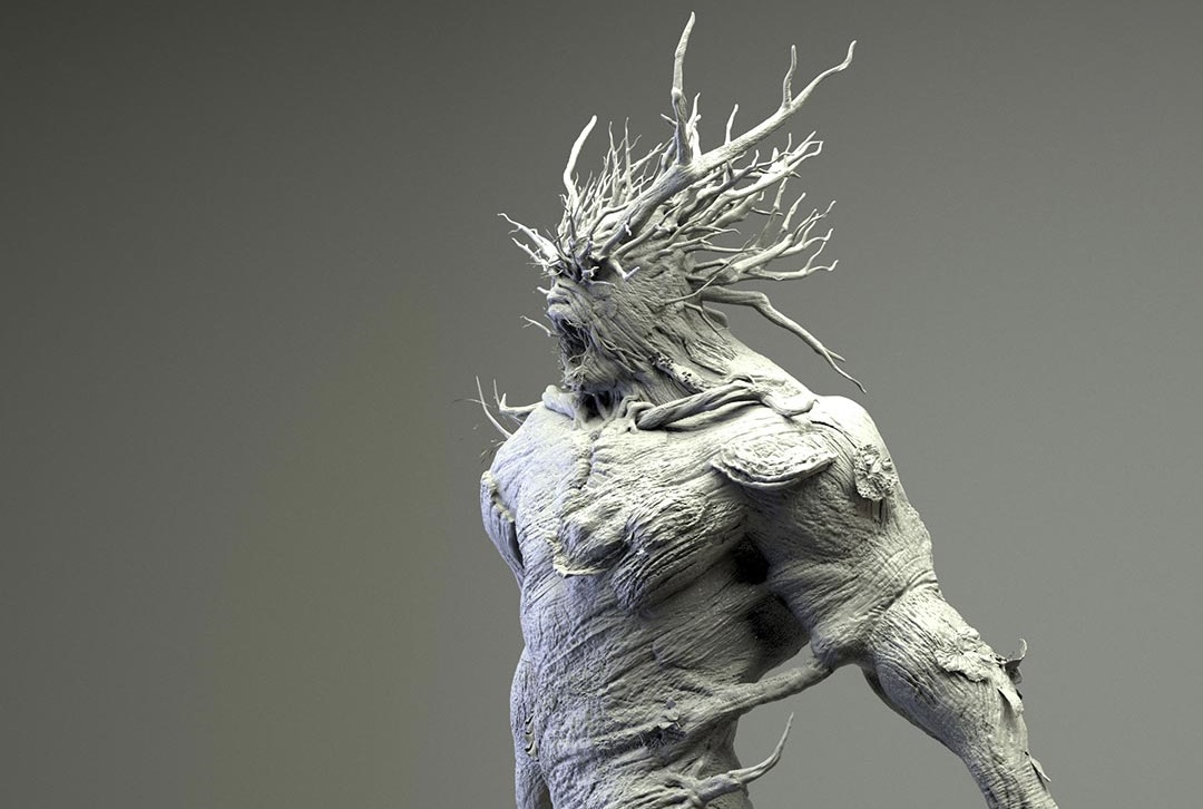
One of the tools that I wrote which wasn’t from work but a personal project I worked on from home on the side was a growth tool for infections or tree roots growing by turning into a geo and other examples that artists can use to experiment with. I created the tool by using a imported geometry and grouping a start point and end points in which the tool will find the shortest path by using the points in the geometry and creating an add node which creates a deformed line, used a resample node to increate the number of points in the line and then used a VDB from points and converted the VDB so it is turned into a geometry. Once I got that sorted I grouped one of the points in the converted VDB and used a wrangle node to added some code that adds a value to the grouped point and finds the point number which is closest to the valued point. I then used a solver connecting to the wrangle node and inside the solver I used another wrangle node in which I created a code that uses the array of neighboured numbers and a foreach loop to increase the value of each 0 valued points when the previous points value (like a infection. When one point increased it’s value the points closes to it increases it’s value too). I then grouped the expression and blasted the geometry so only the valued geometry is visible. The point of the tool is to be able to create a growth simulation using any geometry and have control over where it grows and how much / fast you want it to grow.

This image shows the geometry’s points being used to find the shortest path using the grouped points START and END

this is the geometry that was created from the paths.

this is what the growth in action looks like. The only difference I made here in the tool is to have an option to add a copy to points from a cylinder and then a VDB, convert VDB and a remesh to get that tree branch look.
Database:
A database is a collection of information that is organised so that it can be easily accessed, managed and updated.
database in the VFX industry is incredibly important as it is where all the shot files are for each software like Houdini, Maya, Zbrush, Nuke, etc. the way database works in the VFX industry / Dneg is that we use a online website called shotgun and a custom Dneg tool called ivy. these two programmes contain a list of structured sequences with structured shots in them. each shot contains a Maya, nuke and Houdini file in which you can copy the located file script and paste it in the software instead of just looking for it.
you have two types of data. structured data which is data that has been organised with context also known as a database and unstructured data which is data with no context which is usually found in images data files.
Before and After tasks:
for one of the shows I was given a task to add glass breaking in which I had to use someone else’s set-up and improve on it by adding glass debris and some wood debris. Before the shot was given to me the work that was done only had simple wood and glass breaking simulation with some collision not being 100% accurate. Once I got a hold of the set-up I redone the simulations with updated lidar and character anims and accurate collisions as there was a problem before with collisions not being recognised by the RBD set up. I also added glass and wood debris to make the simulation look more realistic. With the previous version there wasn’t any motion blur so what I had to do is make sure that the velocity attribute is being recognised in the simulation so I can turn on velocity blur in order to have motion blur. Unfortunately I am unable to gather screenshots for this set-up as I wasn’t allowed to use it.

This shows a simulation without motion blur

This shows a simulation with motion blur
Structures and Unstructured data:
It is very easy to understand what structured and unstructured data is as it is in the name.
Structured data: Consists of specific data types who’s pattern is easy to find.
Unstructured data: consists of data that is not easily found.
This is similar to a tidy and untidy room. A tidy room has everything where it should be neatly and a untidy room has everything thrown around.
The way DNEG keep their data structured is by using the system log in / identity to create automatic files when saving. For instance saving a shot makes the system create a separate file with your ID name, a variety of other files inside for saving textures, scenes, etc. And files for each software scene saved. This is used for every machine / user on the server. This was designed to makes it super easy to locate as everyone’s files are structured the same which makes it very hard to get lost. Data also becomes hidden if not used for a while. This is usually to help artist locate files more easily too without having hundreds of files to browse from but once the file is specified then it becomes visible.
Why is this important?
It is very important to make systems like this especially when a company has thousands of employees as not every artists will remember to create separate files or locations for data which can cause problems when other people want to locate other peoples work or the artist forgot where they saved / put them. Creating systems like these make production safer and quicker. Maintenance of work being produced is also very important as the company doesn’t run from just one show each. They run by working on loads of shows at once which are all delivered at different times especially TV. Certain shows are bigger so they take up a lot more space that can makes things slower so by having pipeline maintain the work to match the show deadlines makes production run smoothly and on time.
Data Movement:
The way we move data around the internal system is by using shell on a Linux machine in the terminal. If you would want to copy a file and paste it / move it to as different location you would need to add cp in the terminal followed by the file name and then the directory in which you would want to copy the file over to. We don’t use this much in the industry as all file movement is done by the pipeline. The data architecture is like a tree structure I wrote more about this in the project organisation section below which also shows how shots / assets can move from artist to artist.
Security:
Security when it comes to the industry especially if they are multi-million dollar shows are very strict as they usually don’t allow external drives to be used to collect data even if it’s nothing to do with anything you are working on, external drives are not used in the industry at all. Data is secured on the server and your machine. Accessing programmes that aren’t within the company such as the internet requires No Machine Client which is a virtual machine / PC. You can only access the show files if you are assigned to them by the coordinators.
Render Management
Render management is used alot in VFX as it can get very hectic when hundreds or images are rendered at once. one way we keep everything going is by using render farms. Render farms are high performing computers which are built to generate images for either film, TV or visual effects. It’s a service that puts alot of computing power for a specific purpose to help deliver projects faster.
The first step is sending the project to the farm. At DNEG we have a separate plugin that sends all of our renders and/or caches to the farms and your work is queued up. queued up work is important as it automatically distributes processes to many processors. Each process can be the rendering of one image, some images or even all of them. usually the renders are spread to loads of other nodes (computers) which is typically a client server package. Depending on how urgent the shot or cache needs to be delivered, queues are prioritised. Usually the supervisors will tell you if you’re allowed to increase your priority.
During my time working I had to learn how to use the camera parameters in Houdini as well as how to create the shaders and set-ups. Rendering was a difficult process as I didn’t have any experience rendering in Houdini before so getting use to the camera parameters was difficult for me but I did get the hang of it when I was working on one of the shot from a show in which I had to use a smoke simulation with motion blur. I had a lot of issues as I kept on seeing a particle effect when the density of the smoke was really low and I realised that the reason this was happening is due to the computer not having enough samples which was 3 x 3. I increased that to 6 x 6 and the Stochastic sample to 8 which allowed the low density of the smoke to fade out smoothly so it looks like actual smoke and not like particles.

This is an example of what the smoke sim looked like with the smoke looking a bit like particles.

This is an example of the smoke sim with the pixel sample increased and the Stochastic sample increased.
Throughout my shot I did get feedback which was to change the variation of the smoke sim from adding more / changing the noise to adjusting the sharpness. I also got feedback from my renders to make the sim look more like smoke and less like particles but through trial and error I manage to figure out how to fix the renders to make it look like smoke. If I was able to do the task again I would definitely do it differently by asking someone as soon as I was stuck so I didn’t have to spend so much time figuring out by myself. It did make me learn more about the camera parameters and rendering but it was time consuming.
Render logs:
Throughout my time at DNEG I have dealt with a bit of render log issues and errors that have accrued. One of the issues that is very common with FX is a memory cap which happens when a cache or render exceeds a certain amount of GB and stops the cache or render. The way I fixed this problem is by switching render scripts on the farmer node in Houdini which ranges from 64 to 120 GB or in the export node you can change from one machine to multiple which distributes the cache or renders. Another problem I have faced is that a error pops up saying that the computer cannot find v2 which means that the version you have selected isn’t the latest version but sometimes this happens even with the auto version update on. The way this can be fixed is by using a high number manually in the version, cancelling the render, deleting the version and then redoing the render with the auto version update on which should then fix the problem. These are the main issues that happen with render logs in FX.
Render Queues and Monitoring:
Even though i haven’t had experience in pipeline, during my time working i have had a sense of how things were managed through rendering and render farms.
The way Render queue work at DNEG is by distributing your caches or render frames into multiple nodes but sometimes if all of those nodes are used up then you would be put on a render queue judging by your priority. The priority ranges from 1 – 5 so if you’re on a 1 then you would be queued judging by the amount of jobs on the farm and if you’re on a 5 then you would over lap the low priority people who are queued up on the farm. This is great for the VFX industry as there are times where you would need to render out shots as fast as possible for emergencies so being able to overlap people who aren’t in a rush is a big advantage.
The pipeline team at DNEG are great with letting you know the issues and are quick when it comes to tickets. All of our renders are monitored through how much storage we are using and that storage is then turned into a percentage of how much the farm is being used which they try and always keep near 100% to use the maximum amount of the farm as they can. Any issues are immediately seen as errors which means that you can send a ticket to pipeline, talk about what the issue is so they know whats going on and they can fix it for you. usually if your renders are taking too long in the cue pipline would track the people who are using the most and if those shots aren’t urgent they would slow down their renders so there is enough space for everyone.
Troubleshooting:
I have come across some issues throughout my time creating set-ups. One of them was when I was working on a National Geographic set-up in which I had to create a smoke sim in which my initial plan was to create a volume velocity for a force but through constant repositioning of the emitter and testing variations of smoke I never got the result i wanted. It was a difficult stage as even one of the leads was having issues with helping me as we couldn’t get what we wanted. After doing other testing and getting help from other people I ended up using what Vladimir Popovic taught me which was to add a sphere as a divergence, positioned where the volume velocity was and turn up the value of the force with the emitter slightly lowered which gave me a smooth smoke sim with a clean velocity.
Statistics:
Throughout my time working I did have to optimise my rendering in order to make the deadline. One of the tasks I was working on had to be delivered five days before and I had to deal with a smoke sim which is one of the longest rendering effects so what I had to do is change the pixel sample so the estimated time would reduce and the stochastic sample to decrease the estimate time even more which brought the render down to half, which was too fast so what I had to do is play around with those settings in order to get the best quality at the right time so I can publish it on the deadline date.
Optimisation:
When working with simulations that use up a lot of storage and RAM Fx TD’s always try and figure out a way of using less but keeping the quality which is a big and important part to know. I have had to optimise nearly all of the work as it is always nicer for the company and the show if you use the least amount as possible. One of the tasks I worked on where I had to creating a rigid body simulation, kept on using too much RAM. The way I was able to optimise the simulation by half was by caching out the commute velocity which took a big chunk of the processing away as whenever I tried to do a variation it kept on having to run that at the same time, saving RAM. Another way I managed to optimise the sim was by turning off the debris self collision which again played a big part in taking up my RAM. Once I resolved the issues my cache time was near enough split in half which was great as it gave me enough time to create variations with renders.


Project Organisation
With VFX it does not matter how big the company is they will always have a tree structure. you will have the root. The root is where you will see the lists of shows. then you will have the branch which is the show sequences. Once you go in the sequence you will find the twig which is the shot names and in the shot name you will find the leaf which is the shot file. Each department have a separate tree structure.
It is very important to have a structured system as people who are assigned certain shots can easily locate themselves and if needed, pick up other peoples work.
when starting on a show you would need to set your shot so the server knows where to store all the files. you can set your shot by using bash on linux. or you can set your shot in the software you’re using from the plug-ins the company have made.
Accessing other peoples work is super easy as every file that has been saved locally on a PC has also been saved on the company tree structure so that any artist can access any work if they are allowed to access the shot or show by setting their shot. This is used by many people to pick up work from others or update work for others. for each save even id they are locally are always backed up to the server. This is also passed on from artist to artist by using asset packages that its picked up and updated when work is approved. The company have made a tool that links the updated work by department, shot and show so the updated assets can be imported into a scene. This includes, models, anim, camera, fx, etc.
Versioning is a big thing in the industry especially with FX as different variations of simulations need to be either different versions or different names. it is important to always version up so that production know the progress you have made.
How naming conventions and version control works:
It is very important to regulate naming conventions and version control as people will use other artists work to change, improve or add into their scene so making sure that the correct work is up to date is very important. Artist need to make sure that the scene name is in the correct place as I have seen and used in the past peoples work accidentally being overwritten by test scenes and recovering that work is a waste of time. The way naming conventions and version control works in the industry is by using a tool that goes through the same name your scene is, checks the version and automatically updates your scene or render with the latest version.
Depending on what show you work on, some of them will require big shots which take months to finish. With effects the process is done within the first week or two but if the client wants changes then set-up tweaking would be needed and that’s where a lot of time is spent. Sometimes shows will be extended if the client is not happy or the shot would be redone by a different company.
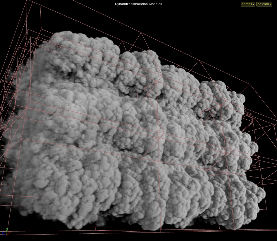
Smoke Simulation set-up:
I managed to finish my work within the deadline as I had 2 weeks to create a smell like effect that gets recognised by an animal. I created a set-up that uses a smoke effect which took me a day to make but because of constant feedback and recaching / rendering it look me exactly 2 weeks to get it to the clients standard. This is usually how my project timelines are as I have learnt throughout my time working to not create a high quality sim at the beginning which makes me struggle when making changes. But by making the simplest effect with a simple set-up, get feedback from the supervisor and make improvement from there so you can get closer to what the director wants each step of the way is a much more easier and efficient way of doing things. The reason set-ups have to be built from the simplest form first is so that it allows it to be easily updated / improved and any changes can be done quickly also if a different artist has to pick up your set-up, it’s a step by step process which makes it neat and easy for the artist. starting off with in built effects tools is great as you can manipulate and make the sim more efficient using existing tools such as a smoke sim. I wrote more about how i built a efficient tool in the set-up review down below.

not my image
This image shows the beginning stage of a smoke simulation with low voxel count.

This image shows a smoke sim with attributes and shaders added which is usually the final stage of a pyro set-up with a high voxel size.
Overall I think my organisation within my projects is pretty well thought out depending on the deadline of shot / set-up as sometimes when the deadline is in the far future I pick up more shots and then it does get a bit too much when I get the deadlines mixed up which is something that I have picked up on and have worked on. I started using not pads to write down what I need to do during the day in order to keep up to date on work and tasks. I do like to take on challenges with work that I am not comfortable with as I get to learnt quicker and better so that next time I get a similar task I will know what to do but it does take me off track with other work as I end up making it more of a priority so having the notes really help me with equally distributing my tasks depending on the deadlines or dailies.
Project plans / Timeline:
Employees Set Project (ESP):
Feedback Form:
Maths
Throughout my time working I don’t really use Vectors, Trigonometry and Matrices so I had to relearn and brush up on my maths techniques for my end point exam.
A vector is a represented as an array or numbers. This array can be assumed in any desired length.

V = (a,b,c,d,e,f)
Where a,b,c,d,e,f are real numbers
The idea behind these numbers is that all together they represent a value or concept that is meaningful in the context of the problem. For example, vectors can be used to represent either a position or direction in space.
Points and Vectors
a point is a position in three-dimensional space. a vector usually means a direction in three-dimensional space. Think of vectors as directions. Points and vectors are very similar as they are both represented by aforementioned.
V = (x,y,z)
Trigonometry
Trigonometry involves calculating angles and sides in triangles and each side of a triangle has a specific name.
The Hypotenuse (h) is the longest side and it is opposite the right angle.
The opposite side (o) is the Y axis.
The adjacent side (a) is the X axis.
Trigonometry involves three ratios which are the Sine, Cosine and Tangent. A easier way to remember these are.

sin x = o/h
cos x = a/h
tan x = o/a

Finding AB
sin 32/8 = 4

find x
cos 4/6 = 0.6
use cos-1 on the calculator
x = 42

Matrices
A matrix is a collection of numbers arranged into a fixed number of rows and columns. Each number that makes up a matrix is called an element.
The upper left corner of the matrix is row 1 column 1 which has a value of 5. Row 2 column 3 has a value of 4.

This is also known as a square matrix as it has the same number of rows as columns which is used in computer graphics for transformations.
the number of rows and columns is called a matrix dimension.
this matrix has 3 rows and 2 columns.
a column matrix consists of a single column but with multiple rows. These matrices are mainly used to represent geometrical vectors.
sometimes you can get two matrices that are equal. in order for them to be equal they have to have.
- The same dimensions.
- Corresponding elements must be equal.
These matrices are not equal even though they have the same elements.


How is maths used within the industry:
Maths is used a lot in the industry and some artist don’t even realise what form of maths they are even using.
Vectors) Vectors are probably the most commonly used in VFX as departments such as layout, modeling, Fx, rigging, shoot, build, etc all use vectors as you use it in 3D software for the positioning and the direction of the point.
Trigonometry) Trigonometry is mainly use in layout, to determine where models will be place so it matches the plate and Fx would use it if there is a effect that needs to land on a specific area like a camera or an object so judging by the angle and the distance of the emitter / simulated object you can use the trigonometry to determine how much force / velocity you will need in order to get the result you want.
Matrices) Matrices are used a lot within the VFX industry especially with artists who use 3D software such as layout, modeling, Fx, rigging, groom. They would mainly use it to apply transformations to match different sized object.
The combination of trigonometry and matrices are used in OpenGL for camera projection in 3D rendering.
Code I have written:
one of the codes I produced was for a simple tool I created for directional growth. The main code for the effect was.

This means that I add up 0.1 for every neighbours that has an infection value bigger than 0 so that it is infected and then I divide the sum by the count of neighbours to form an average.
Personal AR app made with Unity:
This was my first attempt in creating a AR app.
The first stage of creating an AR app was to brainstorm ideas of what I wanted it to be and how it will work. My initial idea was to have a picture of Mario from the game Super Mario and have that be the trigger for a Nintendo DS to pop up above in which it starts playing the game Super Mario. You tap the screen for the DS to turn on and you tap it again for it to turn off.

As it was my first time using Vuforia in Unity, I wanted to do test showing that the image recognition works and that model popping above it works. I also wanted to get used to using Vuforia by watching YouTube tutorials and reading forums. Before starting up Unity I had to make sure that the Vuforia plug in was enable so that I can begin to create an AR scene and use my virtual camera as my laptop camera. When setting up my image target to be recognized I needed to get a license key which I had to get from the Vuforia Developers website as their recognitions are done through an online service. Once I got my license, I then had to create a target image via the same website, import my picture, download the files and then open it into the same scene in Unity. I then copied my license and pasted it into my virtual camera which can then find my target image through the online website, recognize it from my laptop camera and allow me to add any kind of geometry, image or video on top which will then be displayed. In this case as a test I used a book cover and just a plane image of a Nintendo DS that I found on the internet. Once I was able to get that working, I added a cube instead so that I can see how good the 3D tracking works whenever I tilt the image backwards and forwards. When I was satisfied with the outcome, I was able to move on to modeling a Nintendo DS so I can replace the cube.

I wanted to make a low poly DS as it will be used as an application on your phone, so it needed to be fairly simple. I used Maya to for modeling and I created by own textures using photoshop. I began by picking an image of the Nintendo DS from the internet and added that as my template, so the scaling and measurements are accurate. To make the model as simple as possible I used a cube, rescaled it to match the reference and created shapes inside the DS for charging ports, game ports, etc. I then used those to create a Boolean with the cube which adapted the geometry around the shapes inside, creating extra faces and vertices. I was then able to finish the model by adding some edge loops and extrusions to get a more accurate and realistic look. Doing the UV’s for the model was pretty simple as there wasn’t much of the geometry to unwrap so I quickly laid out the important details such as the buttons, screens, power, sound and automatically unwrapped the rest which wasn’t going to be seen or didn’t have much detail. Once the model was done, I began to animate the closing and opening by adding keyframes on the rotation and exported it as an FBX which is the file format that Unity supports.

I created a separate geometry for the screens so I can animate them more easily by adding keyframes to the rotations instead of creating a rig.

This is what the final model of the DS looks like.

This is what the DS looks like once it was animation (this is the rest position).
Once the unwrapping was done, I saved the UV map as an image and imported it into photoshop for texturing. I did have some issues when I exported the textures and importing them into unity as some of the detail was incorrectly placed so I had to go back to photoshop and fix the issues. When everything was working well and looked correct, I was able to replace the cube, import the Nintendo DS, add the textures and copy the animation so I have an open animation and a close one. I wanted to add a feature where whenever you touch the screen it either turns the DS on or off , so what I did was I used a little cheat where I created just the screens and the green light, matched the animation with the Nintendo and only adjusted the position of the animation slightly. when the DS opens the screens and the light are visible and when the DS closes, they aren’t visible as they are hidden inside the geometry making it look like the screen actually turns on and off. Once I got the animations and screens sorted, I had to create a script and import a touch count so that whenever you touch the screen the animation is triggered.

This is the animated on and off screen that become hidden in the geometry once the DS is turned off

This is the animation graph that I had to tweak in order to make it match the animations with the DS.
My final stage to this process was putting it on the phone as an app. I had to use a Mac as I wanted to add it onto an iPhone but usually it’s a very long process, so people do prefer transferring it onto an android. I did face a lot of issues which is why I was unsuccessful running the app once it was on my iPhone. The first thing I did was switching platforms from the PC to the IOS in Unity, adjusting the player setting and building it. Once the building was finished, I opened the XCode file, logged into my apple ID, connected by phone and began the transfer. Unfortunately, XCode had a lot of warnings (1140 warnings) which is probably the cause of why it did not run on my iPhone. From the forums and YouTube videos I have watched to try and fix it but there wasn’t much help out there.

This image shows how exported my app/game for IOS = by changing platforms in the build settings.

This image shows my attempt in transferring my app onto my IOS phone by using XCode which is exported once you change build in Unity. As you can see I have 1189 warnings.

I managed to add the app on my phone but I wasn’t able to use it as it kept on crashing whenever I open the app.
How maths was used in my project:
Throughout the process of doing this project I used a range of maths to help me such as vectors and matrices to determine where the model will be and how much it needs to rotate in order to get the best view of the model and it’s function. I also used maths to help me with the animation graph so I can match the animation speed of 2 objects in which I was very stuck with when just fiddling around with key framing the translation and rotation but by using maths and the animations graph I was able to fix this issue very quickly.
Software Design
Software design has always been important to the industry especially when it comes to deadlines. Software design gets involved when there is an issue to solve or to make life easier for other people using the software for instance. Every company have their own plug-ins and tools that are used for specific purposes in which the artists can access (depending on which software it’s built) to help them achieve the tasks quicker and more efficient.
A example of this is Houdini. In order to create a normal particle simulation which would require a POP node and inside the POP node you would need to add a pop object, pop source which is attached to the pop solver which is then merged in with a static object for collisions and attach that to a gravity node and that doesn’t include a pop attract to manipulate the behaviour of the particles or a pop curve so that the particles can follow a guide. instead of me adding all of that I can use a tool that was created by the company which only requires one node that all of the parameters as the Particle sim which reduces the time I spend working on the sim and it’s easier to locate every parameter.
The stages of creating a set-up:
First step is to create you basic effect such as water, smoke, fire, destruction, etc.
Second step is to manipulate your effect.
Third stage is to test with the parameters in low quality so you can get the variation you want.
fourth stage is to cache out your simulation on the farm in high resolution.
fifth stage is to create the shader for your cached simulation and begin doing render tests.
sixth stage is to add notes on important parameters and explain what the nodes do so that the artist can navigate around the set-up easily.
seventh stage is to release your set-up for artists to use.
eighth stage is to gather feedback from the artists who have used your set-up and start making changes / improvements
ninth stage is to release the set-up again for use once the feedback and improvements have been made.
It is very important to design your set-up before developing it. Depending on what type of set-up you have to create it all starts off with the basics of creating an effect for instance smoke, destruction, water, etc. And then move on to manipulating the effect to whatever you need the effect to do. But you would need to think about your approach to the set-up (usually writing down certain nodes you would use helps), how will you make it easy for the user / artist to understand / use and how can you create the set-up so that it is easy to create variations or changes.
Plans for set-up:
One of the set-ups included a fire simulation on a animated geo. The plans was to create a smoke sim set-up with different parameters and add a smoke shader with certain attributes being different colours such temperature and cooling.
Work flow diagram:

This is usually what a Fx set-up diagram looks like.

This is an example of what a obj Fx diagram looks like.
Red: Red resembles the first stage of a set-up by creating geometry or importing and converting the geometry from the asset package.
Resembles the render nodes and camera.
Yellow: Yellow is the middle stage of the set-up where all the custom attributes are named and the preparation for the simulation is made which include custom collisions, velocities, constraints, etc.
Resembles the light nodes.
Green: Green resembles the final section of the set-up which is where the simulation testing, fixing, caching and updating asset package takes place as well a materials and textures if needed.
Resembles the simulation nodes.
using workflow diagrams and prototyping are incredibly important when helping to make set-ups much more efficient and better as every artist has their own unique way of creating a set-up and use their own techniques in creating them. This helped me a lot with shadowing and using other peoples set-up as it taught me how to combine different techniques that I’ve learnt from different people into my own style of creating set-ups which is exactly how workflow diagrams and prototyping help in creating better solutions by gathering techniques from other artists and implementing them into set-ups. Feedback is very important to creating set-ups as it allows the TD to add new features to that would help artists understand better or even make it easier for them to use.
Research:
The research for the set-up was a bit difficult as referencing large scaled fires on small scaled things doesn’t exists so we had to use what we could with comparing small fire on moving objects such as burning tires or sticks on fire to large static fires such as burning buildings and burning trees. Due to shot being unrealistic we had to use our imagination to picture what the effect would look like from the references we’ve gathered.

This images is an example of the references we were looking at

This images is also an example of the references we were looking at
Development and solutions:
Throughout the time creating the set-up we came across a range of issues what we had to resolve using alternatives which did lead to the effect being change. The main issue that came up was that the animation was too fast for the simulation and even with loads of substeps the caching took too long. Our first attempt of resolving this was by slowing down the animation and running the sim normally with only one substep but it kept on making the simulation look too sped up when we match the normal speed of the animation and the effect so we solved the problem by caching the simulation out with a static model and then using a point deform to it matches the positioning of the animated model with a trail so it gives the illusion that the smoke sim is simulated on a animated object. This was great as it met the requirements the intended user wanted which was to be able to change from a static position to a animated one using the same sim and to have control of the fire trail which we gathered from our first test of the set-up. It was great that we made the set-up with so much control on it as it allowed the set-up to be picked up for extension if someone wanted particle sim instead of smoke sim.
Investigating existing solutions:
On one of the shows I had to create a engine thruster in which I used a simple smoke simulation with loads of turbulence and a fire shader. The Problem was that the turbulence could never be calculated at the value it was so the solution was to cache the simulation out normally, adding a retime making it much fast and then caching it again. Although it was a simple set-up I spent most of my time doing variations to get the right look. After doing some testing with a similar effect I discovered that I could’ve used a bunch of curves on a circle which matched the circumference of the engine and met the end point curves together, use a pointVOP to create a noise / wave effects in which I can control the speed and turbulence and turn those points into a VDB this would’ve given me the same effect with much more control in a shorter amount of time.
Development Road-map:

This is a development road-map that i drew out just to show what the process of creating a set-up looks like. I split it into 5 weeks as that’s how long a usual shot would take from scratch. Creating the basic effect such as the emitter and the solver with added custom parameters would take around a week. Usually the first day would be planning out what and how you’ll do it. Testing would be involved in the middle just to see how variations look. second week would be manipulating the effect by making adding curves for the effect to follow or just finishing the set-up adding caches, creating shaders, making it more efficient / simple. Third week would be testing out the set-up by doing variation, doing the effect on different / animated geometry, test renders and the fifth week would be getting feedback from the user such as maybe some nodes aren’t working correctly or the user gets lost easily in the set-up and make changes to match what the user wants. sixth week would be the final release of the set-up / tool.
Scripting
Scripting is a variety of languages a computer uses by creating a series of commands to tell the programme or PC what to do.
Python: Pyhton is one of the most commonly used scripting language within the VFX industry. Python is a interpreted language therefore it can only be used for developing GUI apps, websites and web apps. Python is meant to be easier to read than most languages and easier to learn. each language has similarities but there are always differences when it comes to comment and closing the code. with Python comments are used by adding a “#” before the sentence and closing a code you would add a “:”
Example:

Shell: A shell script is a series of commands for a UNIX and Linux based operating system. Shell is used a lot in the industry as it is easy to get around and saves a lot of time. It can be used to run software, save / delete files, move files, create folders for file, etc. As shell is used to locate yourself around the PC the code is closed by running the command.
Example

VEX: VEX is a more efficient language for writing custom shaders and nodes. it is based on a language called C and C++. Houdini uses VEX as they are needed for generating light, displacement and many more. creating custom nodes in Houdini is a big thing in visual effects as creating specific effects for certain shows takes alot of setting up so for one node to be able to do all of that really saves time and helps other artists understand easier. VEX is very similar to Python except it uses “//” for comments and “;” to close each line of code.

Code I create for my personal AR app:
for my personal AR app I used CSharp which is a language used in unity. The code I wrote was to use the touch control to make it trigger the open and close animation for the DS. The screenshots show code for the DS (animHDD) and the DS screens (animHDD2).

I used on the number pad 1 as a test to see if the code works and then used .GetTouch once I was comfortable with how things were.
Low poly Procedural dungeon tool for game:
During my time work at DNEG, I did get some time to be able to create my own procedural dungeon for games in houdini. I never started with a design or a plan about how it’s going to look like. What I did have was a rough concept of how it could look like in my head.
The image below show that I used a scatter of 500 for the floor plates I created four different kinds of tiles and I put them in a switch. instead of the switch being from 1 – 4 I added the code fit01(rand(detail(“../foreach_begin1_metadata1/”, iteration, 0)),0,4) and I put that into a copy to points in a foreach loop which is connected to a grid who’s channels are from a transform that has a noise motionfx for each frame (the scale changes each frame). I changed the scale and that amount of points it has so the tiles can sit on it equally. The copy to points has a stamp for the scale which is fit01(rand($PT), .5, 2) when this is connected to the foreach_end it randomises the four tiles and randomises the scale from .5 to 2 on each point of the grid. I then used a mountain from the grid and used it as a bounding object from the foreach and I blasted the selected group points. I added a poly extrude to hide the gaps but you can use a polycap too. The reason I did this was to add a broken tile look.


The first tile image show how it looks after using the cracked tile technique and the second tile image what It looked like before.


The images above show that With the grass side of the dungeon I used a similar concept to the floor tiles but instead of using a foreach loop I just used a copy stamp and added some VEX in the stamp inputs which are. Scale) fit01(rand($PT), 0.1, 0.5), Rotation) 360 * rand($PT), Model) rand($PT) * 4, Rotation X Y) 45 * rand($PT). this allows me to randomise my scale, rotation and model for each point. I then used a transform before the copy so I can control which stamp I want for which parameter. For instance, on the scale parameter I added a stamp(“../copy9”, “scale”, 0)which lets houdini know that I want the scale stamp code to work on my scale parameter.
to position the grass, I wanted them to be in the gaps and cracks of the dungeon floor so it looks old and overgrown. The way I did this was by using my channelled grid and two scatters. One has a low scatter point which is grouped by all of the other assets as they are used as bounding objects and then the intersecting points are blasted. I then used a low poly sphere and added a copy stamp and had a scale stamp for the sphere so there are different scaled spheres for each point. I used a group node to group the spheres and the second scatter node from the grid grouped it again but using the assets as the bounding objects and I blasted the colliding points. Finally I used a copy to points with the simple grass models.


The images above show that with the bottles in the dungeon I used similar nodes like the rest in making it procedural but there were some collisions I wanted to fix as the scatters go over different assets. What I did was used the object merge to get the assets , use a scatter so I an generate points and then a vdb from particles and a vdb smooth. What this allowed me to do was to use it as a bounding object in the group node so I can blast the unwanted points.
for the game style. I wanted to have simple and solid colours but it also being low poly. What I did was create an attribute for each procedural point for the dungeon and I named it by the asset. What I did next was use a colour node and selected ramp from attributes, added the bottle attribute from the points class. This gave me a choice of ramped colours scaling from 0 – 1. I then used a copy stamp and ticked the box use template point attribute in the attribute window and connected the colour node to the copy stamp from the bottle models.

This image shows the geometry spreadsheet with different values of RGB for each point.

The way I was able to export the colour attribute was by adding a material node for each grouped asset. I then used a material network, created a material builder node and inside I used a bind with the name Cd so it knows which attribute I wanted exported. I then used a bake texture in the ROP network and in the node I added a extra image place with the vex variable and the channel name which is bottle, tiles, wall, etc. In the baking window I ticked disable lighting/emission. Unwrapping window in the UDIM post process I put No Post Processing.

This image shows the nodes that I used so I can export the UV Cd attribute as a image.

I used a bind in the material builder so I can tell Houdini which attribute I want to export.

These are the 3 obj nodes that are used to export Cd attributes as image files.
Maya Building project
For our Maya building project, we were told to create a simple procedural house / building using just python in Maya. At work I deal with only Houdini and simple Nuke in which I would only use VEX so completely changing language was a bit tricky for me. But after messing around with python and using the internet to help me, I managed to create a rough procedural building by randomising the height with a certain amount of distance in which the cubes can generate.


Troubleshooting during project:
I did have issues is exporting the colour attributes as image files. I was so stuck on it that I had to bring it into work and ask around, luckily one of my friend Andrew Browne helped out with exporting. We kept of getting the alpha channel when we render out on Mplay and not the Cd channel which was the problem we faced. Our first option was to try and change the bind export type from a vector to a float but that gave us the same result. After a testing out different settings and parameters we realised that the actual geometry wasn’t the problem but the ROP and the material were by changing the export from when input is connected to always with the context being the surface and the channel name the same as the Cd name in the geometry which fixed our problem and gave the result we wanted.
Principles:
set-ups have the same principles as Software design which have many principles.
SRP: single responsibility principle means that each class can never have more reason to change meaning that classes are designed so stand for one purpose.
OCP: open / close principle meaning that software set-ups should be open for extension and close for modification. Closed meaning once a software is made and it’s been tested and developed it should only be used for fixing bugs. Open meaning that you should use code to extend in order to introduce new functions.
LSP: Liscov substitution principle means functions that use pointers of references to base classes must be able to use objects from derived classes automatically.
ISP: Interface segregation principle means that the service interface which is shown to the client / artist should only contain the methods they need not all.
DRY: Don’t repeat yourself means exactly what it says. Each code should only occur once in the entire system. This helps with maintaining and reusing code.
KIS: Keep it simple means that each software should be as simple as possible and to avoid unnecessary complexity.
YAGNI: You ain’t going to need it means that software should only be made when it is needed never before.
Using existing tools to create small scaled tools:
At work I try and use these principles as much as i can when creating a set-up. Creating small scaled tools using existing pipeline tools and libraries is used a lot when creating set-ups in Fx. For example I was given a tools that randomly generated car parts, glass and wood from a particle simulation. What I had to do was add a small tool inside which allowed artists to use points from curves as emitters. I also added a emitter time so they can modify when the particles will emit for each point. This is also used as a separate tool for other particles simulations.
Computing
PC Components:
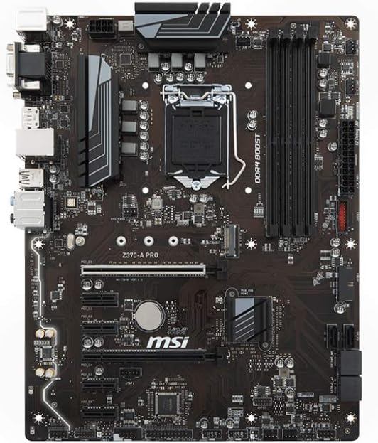
Motherboard: the motherboard is the most important component of the PC as it is where everything else is connected to. it’s designed to hold other components and connect them to one and other so the PC can know what to do.
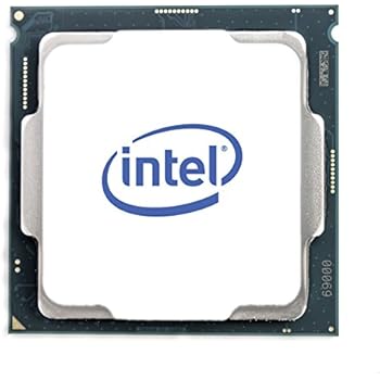
CPU: The CPU also known as the central processing unit is responsible for doing all the calculations needed by the system. It is literally the brains of the PC. Rendering uses a lot of it’s power which is why it is really important to have a good CPU. A CPU can have multiple cores and the more cores you have the quicker the processor can perform operations. A CPU can feature from two cores to twelve. Servers and workstations could feature up to 48 cores. a big problem with the CPU is the heat. It can get extremely hot which is why you need a good cooler above it to stop it from EXPLODING!! (it doesn’t explode) but it can get really hot which can damage important components.
GPU: The GPU also known as the graphics processing unit is similar to the CPU but it is designed to perform complex mathematics so it can display images. It is used to show anything from videos to renders from 2D and 3D software. The GPU help with showing how much FPS it can display meaning how many frames it can produce per second. Extremely good GPU’s are used in the industry as it allows artist to view heavily cached work or high definition textures without a incredible decrease in the frame drop. The GPU is really good when it comes to real-time rendering which is mainly used in game engines such as unity, unreal, etc.

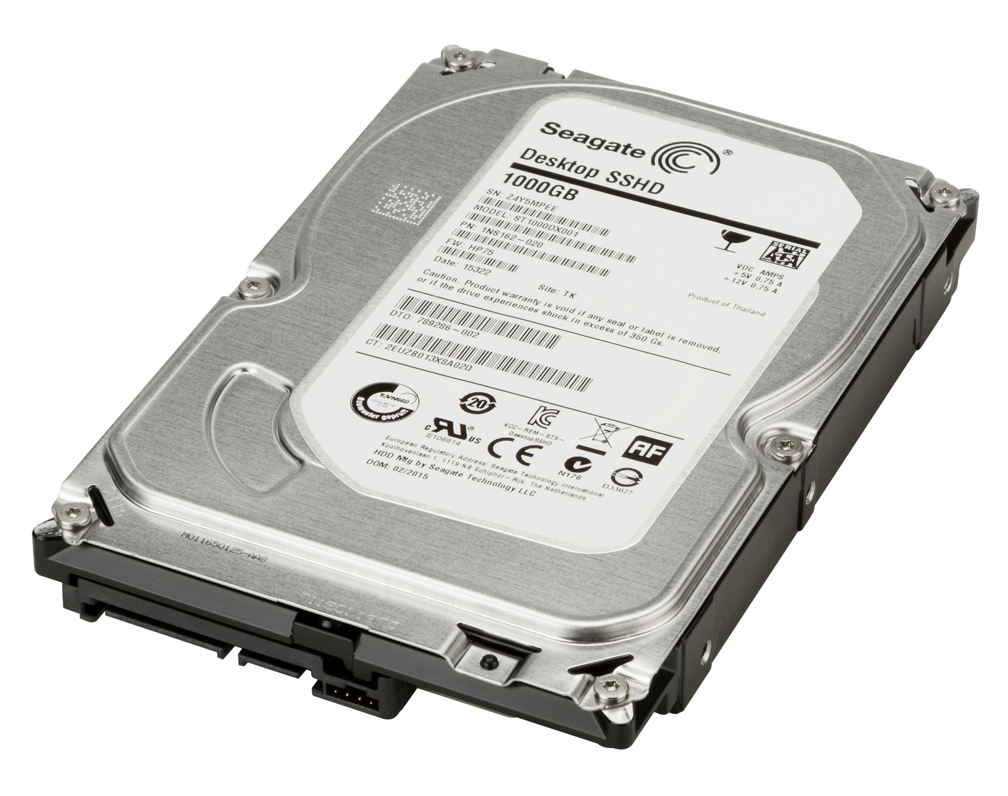
Hard Drive: The hard drive is where all the permanent information is stored such as programmes and files. Hard drives are also used in the industry for servers so that all the work from shows can be stored and archived securely.
RAM: The RAM also known as the random access memory is responsible for storing temporary information whenever you open things such as software, programmes or files. The more RAM you have the more programmes you can open at once. The RAM is very important to have but you would have to be careful with which one you pick as not all CPU’s can handle the amount of voltage high quality RAMs produce so if you want to have an incredible RAM you would also need to check if the CPU is able to deal with it. The higher the clock speed of the RAM the faster it processes data.
Power Supply: The power supply is in the name. It powers every component in your PC. It is really important to have a good power supply as some people would want just need enough electricity to power but sometimes when you have to upgrade your PC you would also need to change your power supply
Components most important in VFX:
CPU: The CPU is mostly important to FX artists and Look Developers as effects uses the CPU when caching simulations. the more memory you have on your CPU the higher quality simulations you can cache. Look Developers need a good CPU as rendering uses alot of it’s memory.
GPU: Look Developers need GPU as well as CPU depending on the software you use, most of them use CPU when rendering but it is possible to change the renders so it goes to your GPU instead.
RAM: The most important components for a FX TD is RAM and a lot of it is needed in Fx as lot of simple local caching is done for small testing at the beginning of set-up and all of those caches build up which end up using a lot of RAM. Another component is CPU which calculates the small simulations that are done locally before feeling comfortable with the variation and putting it on the farm.
You can see which component is damaged pretty easily if you know what each component does and how they work. The motherboard effects everything so if there is a problem with the mother board the PC would just not turn on. CPU’s are easy to see as it effects your whole PC too. Slowness when either rendering or caching can be seen as a issue to the CPU also heating can be a issue and damage your CPU if you don’t have a good cooler. Luckily PC’s now can tell you how hot your processor should be and how hot it is. You can also put a maximum percentage of how much processing you want your CPU to use which is good so you don’t over clock it. GPU is also simple to see as you can just check how your FPS is in the view-port of your software. If it is really slow when processing caches then you might want to upgrade your GPU. Cooler can be seen as damaged or not good if your CPU is overheating a lot which means that the cooler isn’t doing a great job but can also mean that you have may have too much dust if you haven’t clean it out which i recommend doing every 6 months. Hard drives are a bit tricky to see as damaged as not a lot of them are but when having a damaged hard drive your files can be miss-located or some files can corrupt easily or be overwritten which has happened to be before and i had to replace my hard drive. RAM is easily seen as your PC can read how much RAM you have so if you have less than you should it means that either your RAM isn’t put int properly or it is damaged. But with built PC all of these component are very easy to fix and replace.
How are these components used at work:
When caching a simulation the process behind caching contains one component and that’s the RAM. Caches are temporary data that are stored in the RAM which can then be saved on a local drive or a server. Render farms have a lot of RAM in which caches are distributed between multiple machines to cache faster.
The CPU and GPU are very important component in the industry as they render the pixels on the screen to create images from 3D software. Rendering requires OpenGl which is a API who’s purpose is to take data from the CPU to the GPU
On one of the shows I worked on I had to create a huge particle system using a simple particle emitter which a incredible amount of velocity and collisions which required a lot of substeps and particle count. The big issue that we had was the simulations took too long to cache in order for us to tweak. this used a lot of RAM and used up a lot of the farm which had to be optimised for the sake of the deadline and the director. What we did to make this happen was to split the simulation into four sections and use a wedge tool to cache out each section at the same time, cutting down the time it takes for the simulation to cache on the farm by half but we wanted to take it a step further and got rid of the collisions for the points colliding with each other, allowing us to add more particles without effecting the time it takes for the simulation to cache and uses less RAM when running the simulation on the PC by 3/4.
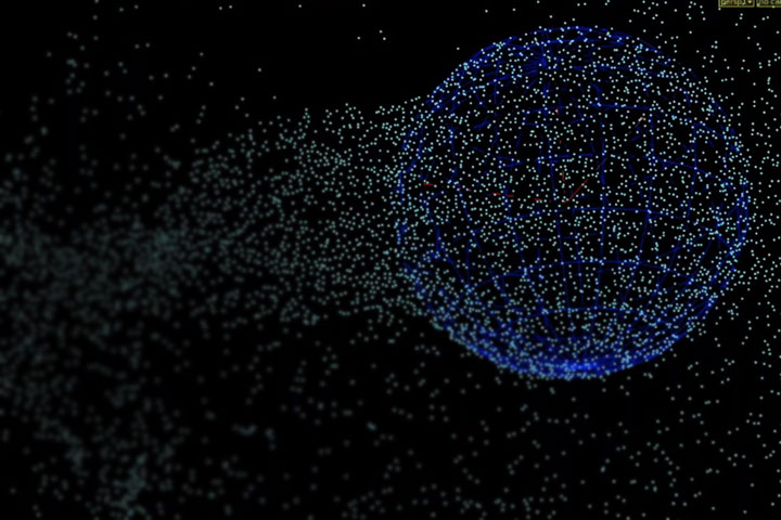
This image shows a sphere emitting particles.
How are these files stored?
The way these files are stored is by a hierarchy or directories, like a tree which is known as a Inode. These are used to organise files on a computer. At DNEG as we use Linux the directories start with a root directory which is seen as a forward slash which contain sub directories in which they too can contain more sub directories. The files are a named collection of the users connected set of data which is kept in storage. This information doesn’t automatically contain any sort of size or directory unless someone adds that to the data. Information about the file is different to the information in the file and this is called a metadata. There are two ways in which the file system can run out which is by consuming all the space or using up all the Inodes. This is how the the server is able to store centralised information to a distributed database.
VFX Craft
Effects Department (FX)
The main department that I have been involved with as an ATD ( assistant technical director)is FX. A FX TD (effects technical director) is responsible for creating 3D simulation set-ups so that FX artists can pick up set-ups and create different variations. The main software the FX department use is Houdini and some Nuke for slap-comps. A big issue the FX TD faces when creating set-up is mainly collisions with other objects if the simulations is a fluid, particle, bullet or even smoke as they all react differently to objects and are calculated differently as bullet tends to be heavier there for falls quicker which can irritate the collisions with other objects but a smoke sim tends to be slower so the software has more accurate simulations with collisions. The way the TD’s deal with this issue is by testing out the substeps in the sim (how many extra frames in one frame) allowing the software to create a more accurate calculation. Another big problems that TD’s face are making set-ups work properly with other geometry by just importing obj’s or alembics. They way this can be fixed is always different as usually it is to do with the actual obj or alembic cache but sometimes it’s to do with the nodes that convert the cache or a obj into an unpacked object.
During my time at DNEG as a FX ATD I have been put on some shows like Hobbs and Shaw, Bramastra and Fast and Furious 9. Working on different effects such as fire simulations, smoke simulations, particle simulations and sparks. The way this was done was by using Houdini to create set-ups for each effect made.
Shoot Department
The shoot department is responsible for turning lidar scans into digital asstes for layout and photographs on set for stitching and HDRI’s. My role in this department was fixing the stitched images for HDRI’s. The programmes they use are jigsaw for storing images and Stig for stitching the pictures to make HDRI’s. a big problem the shoot department face is the process of getting the lidar scans sometimes mess up and they end up missing out some detail when it’s converted into a digital asset.
I was only put on Shoot for around 2 weeks but I did learn a fair amount about how things work in that department. I was put on Fast and Furious 9 to stitch and layout images for HDRI’s. I used Jigsaw to locate the images that I needed to work on and then I used Stig to stitch the images together and straighten them out.
Behaviours
1. I Had to lower down a particle simulation by using a mesh which had a volume velocity. The problem that came up was that the particles weren’t following the guides so what I did was I cached out the particle sim using the volume velocity and i then used a point deform from a mesh to correct the direction the particles were going.

2. I was working on a set-up that one of the TD’s made to create a particle wall simulation. I discussed with a group of colleagues what the best look could be for the shot. We came to a conclusion of adding a transform to flatten and squish the cache so it adds more detail and fits in the shot better.
3. I created a fire ground iteration on one of the shots. I spent a bit more time working on it as it didn’t look right on the slapcomp with the other effects in the shots even though other colleagues said it looked good. I began to do more experimenting by changing the variation and density of the fire and smoke. I picked the cache I liked the most and it turned out that it was exactly what the client was looking for.
4. I was working on around 5 shots and the deadline was in a week so what I did was I looked at what I had to do for each shot so my plan was to start on the bigger shots first and finish off with the smaller shots which have less priority.
5. I really enjoyed moving rooms and shows as I got to work with other incredibly talented artists and meet different people which I have learned a lot from.
6. I was able to create variations of fire simulations with turbulence that matched the wind in the shots. I identified the wind by looking at the other objects in the shot such as clothing and other materials that are effected by the wind.
7. During my time on each show I’ve spoken to alot of TD’s who’s set-up I have used and asked them to explain what they did with each node which really boosted my skills as I’ve seen what style other artists use and how they overcome the issues they faced.
9. During the times that I’m not assigned to shows I would always go on the DNEG tutorials and training pages. I would also check out wikis on other peoples set-up and learn from them.
10. I am always spending my time asking question about certain things that I could improve on or things that I don’t understand so the next time I do the same job I will be able to do it quicker with higher quality work. I organise my shots before I start on them by figuring out roughly how I will be doing each shot so that when I start it I know what I am doing.
The people I worked with and what I learnt from them
I didn’t learn a lot from my line manager as it kept on getting changed from the beginning due to them leaving and being replaced several times. My latest manager is a head of department who helps me a lot with linking me to other people who can give me the skill that are required and I haven’t been able to make big progress due to me being put on Furlough since April.
Tamar Chaterjee:
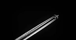
I learnt how to create contrails for engines and wings of planes without using a simulation but just VDB which is quicker and you have more control over effect.
Vladimir Popovic:
Vladimir has taught be the most as I have spent the most time working with him on several shows. I learnt how to create particle, smoke and debris simulations in which I used on a National Geographic shot that I worked on after.
Jonathan Davies:
JD was one of the leads on a show I worked on and he didn’t teach me how to create a whole simulation but taught me a really important technique which I constantly used in my shows after which was volume velocities which is a variety of points in space that have a certain guild that is used as a force for particles and volumes.
Lukas Niemczyk:
Lukas was one of the first people who taught me a effect and It was how to create sparks which I then used in one of the shows for bullet hits and scraping metal objects.
Florian Koebisch:
Florian taught me how to create debris but for different objects such as glass, concrete and car parts which I then used for glass shatters on one of the shows that I worked on later on.
Shahid Malik:
I have learnt how to cluster cache meaning I can cache section of the simulation allowing me to cache faster and increase the quality of the sim.
Set-up Review:
Working on one of the shows I had to create plane engine contrails so what I did was I started off with creating a central point for the back of each engine and added a solver so the points are trailed throughout the animation. I then created a line which connects to each point, following the animation. resampled the points so there is more of them and used a point VOP to create noise and and a drag judging by the age of the points (bigger the age the more drag) and then used a copy to points connecting to the sphere with a mountain node to making it look spiky and fuzzy look. I then used another pointVOP to allow the spheres to increase in size again judging by the age of the points. Turned it into a VDB and cached out the sim. Whilst caching out I realized that the sim took too long to cache so in order for me to create a more natural look and more optimised, I used a colour ramp that fades the points in and fades them out. I then used a blast which deletes points which have a Cd of 0. After that I implemented the fade into the density of the VDB. Cached that out and rendered the scene.
My supervisor reviewed my renders and my set-up and gave me feedback which was to make it even more optimizable as the cache and the renders took longer than 15 hours. What I did was I used what Shahid taught me a cluster cached the simulation by splitting the sim up into 10 different caches with the same voxel size which I was going to change using a density ramp which would decrease the voxel size and the quality of the effect. I didn’t need to do that as I cluster cached 10 simulations at the exact same time which saved time and gave me a really good quality result. My supervisor review it again and approved my set-up one I tweaked the variation of the contrails.
This image shows a view of how cluster caching works. Each red square is a separate cache.
shows i worked on
Hobbs and Shaw
During my time working on hobbs and shaw I learnt alot doing simple effects as it was my first show. The effects I created were bullet hit effects which was created using a particle solver with certain particles having the same ID which meant that we were able to connect them using a add node creating a spark looking effect. I also created fire using smoke solvers where I was able to add / adjust the temperature and burn.

Bramastra. (not released yet)
Unfortunately due to my NDA I am unable to talk about any effects work I did.

Fast and Furious 9. (not released yet)
Unfortunately due to my NDA I am unable to talk about any effects work I did.

National Geographic
working on a National Geographic show was very interesting and probably the peak of my understanding of smoke solvers as I was the only one creating the set-up. The set up I had to create was a jaguar smelling prey so I had to create a visualisation of the smell. The way I did this was by using a simple smoke solver, adding as velocity that is dragged by the nose which I then separated into a normal map by turning it into a geometry, a particle sim by using the smoke as a velocity on the particles and a normal smoke sim. I then used the normal map as a distort, the particle sim I added a blur and the smoke sim was toned down a bit. I used Nuke to adjust the fx and blend them into the shot.
what effects I have created throughout my time working
sparks
particle simulations
smoke simulations (Fire, smoke, contrails, jet thrusters)
destruction (debris, fractured pieces / wall breaking)
work we did with Henry Dean
adding value to a colliding object and deforming object using that value.
Henry who works for sideFx came to talk to us about the Houdini software and gave us a mater class on how to deform a object with a certain value. I was used to Houdini as I use it everyday at work so I had a idea of what he was going to do. We first used a test animation that is built into Houdini, we then added a grid underneath the test animation just enough to collide with it. We added a attribute with a certain value to the grid and animation, transferred the attributes from the animation to the grid so that whenever the animation collides with the grid the value around the grid from the collision changes. We had to use a solver so the value of the collision stays from the previous frame. I then added my own little twist and added a @P.y = – @(solver transferred attribute); to a point wrangle which means that when the solver is working, the valued collision changes on the position Y axis on a minus value. I then fractured a copied grid, used a assemble node so that the pieces are named accordingly and I added it to a point deform along with the valued relaxed grid and the valued deformed grid. I then used a dopnet to create a simulation with a geometry wrangle and put in a simple code.
if(@(collision value) > 1 ) i@active = 1; else i@active = 0;
This means that whenever the colliding part of the fractured grid is above the value of 1, the simulation for that part will run.


I then changed up the simulation by using the position wrangle @P.y = @(solver transferred attribute ) so that the point deformer is on a positive value. I added a attribute on the animated test model called active frame which was a integer and has a default value of 10000 but it’s actual value was $F which mean frame number so what ever frame you are on, the test model’s active frame value will be the same. I then added the same attribute to the fractured grid, under point deform but instead of the actual value to be $F it is set to 10000. I then added a solver with a object merge which is linked to the null of the test animation. Connected that with a transfer attribute of the active frame and a wrangle which collected the minimum value of the attribute “active frame” which allowed the change in value from the collision of test animation to the fractured box. To be able to add these value into the simulation I had to add a geometry wrangle in the dopnet and use the code
if(@Frame>=@activeframe)
i@active = 1;
else
i@active = 0;
this means that if the frame is greater or equal to active frame then the active simulation will be 1 which mean the simulation will run but if not then the active simulation will be 0 the the simulation will not run so only the points that have the same value or less than the frame it will run.
Work we did with Ceylan Jawara
Seylan, who is a cg supervisor and was a Creature TD at One of Us came to talk to us about her experience as a supervisor and to teach us some stuff she did as a Creature TD. We started off with having a simple fox animation that Seylan got from her studio who kindly allowed us to use it. We exported the animation as a alembic and imported it into a empty scene in Maya. We then duplicated the mesh so we can deform it and added whiskers to the fox using xgen and custom guide curves. (when you duplicate a alembic mesh, the animation is lost) Seylan got us to use a blend shape on the duplicated mesh with the original alembic. This means that due to the mesh having the same amount of polygons, the duplicate was able to follow the moving geometry. What we then did was add a automatic muscle structure that Maya has built-in which means we were able to add a giggle on the skin / fat of the fox. what else we were able to do was add another blend shape but sculpt out the defined muscle when the fox walks which allowed me to change from the original to the defined so what I did was add a key frame for whenever you would see definition in the fox as he’s walking. The way I was able to know when you can see definition was through reference on the internet. I was very comfortable with doing whiskers as I have dealt with xGen before but doing the blend shapes and muscles was very new and interesting to learn.


Jurassic World Talk
I went to a Jurassic world talk which was free and was funded by Houdini. The talk involved some of the breakdowns from ILM presented by the VFX supervisor for Jurassic world. The talk was extremely interesting as I got a insight of how communication between the director and the VFX supervisor is. Sometimes the director has a very clear image of what he wants and some directors are very flexible with new ideas. The supervisor also showed us some of Steven Spielberg’s Easter eggs he put in the movie. He also showed us how they introduced mixing in some parts of the dinosaurs with cg and some parts with actual on-set robotic dinosaurs which was super inspirational as it brought both types of production art together. It blew me away how many people didn’t know which was cg and which was real, showed how well and how much hard work was put into this movie.
The Aeronauts Talk
we went to see a free screening and talk of the 2019 movie Aeronauts which was a very intense and inspirational movie based on a 2013 book by Richard Holmes about the highest point a hot air balloon / person has ever gone, piloted by James Glaisher.
The talk after the movie was very interesting as the director and writer, Tom Harper and Jack Thorn came to tell us their process of making the movie. The screenplay took around five years and the production companies instantly took it but unfortunelty throughout the process they lost some control of the movie so they weren’t too keen on talking about the VFX much. Apart from not hearing much abou the VFX, the movie and the talk was such an amazing experience to have.
Vertex
the other apprentices and I visited a VFX event called Vertex which was an incredible experience as we found out amazing breakdowns from movies that milk studios have done by using cloud rendering and they explained the pros and cons about cloud rendering such as it is cheaper to use and you have the exact same control as owning a render farm but it is also hard to keep it consistent as other companies use it and it can slow down / stop your renders.
we have found out about other new software such a Modo which is like maya and blender. we met Tom Box who is the co founder of BlueZoo which was very inspirational and motivational hearing his thoughts about the VFX industry.
VFX ATD Check list:

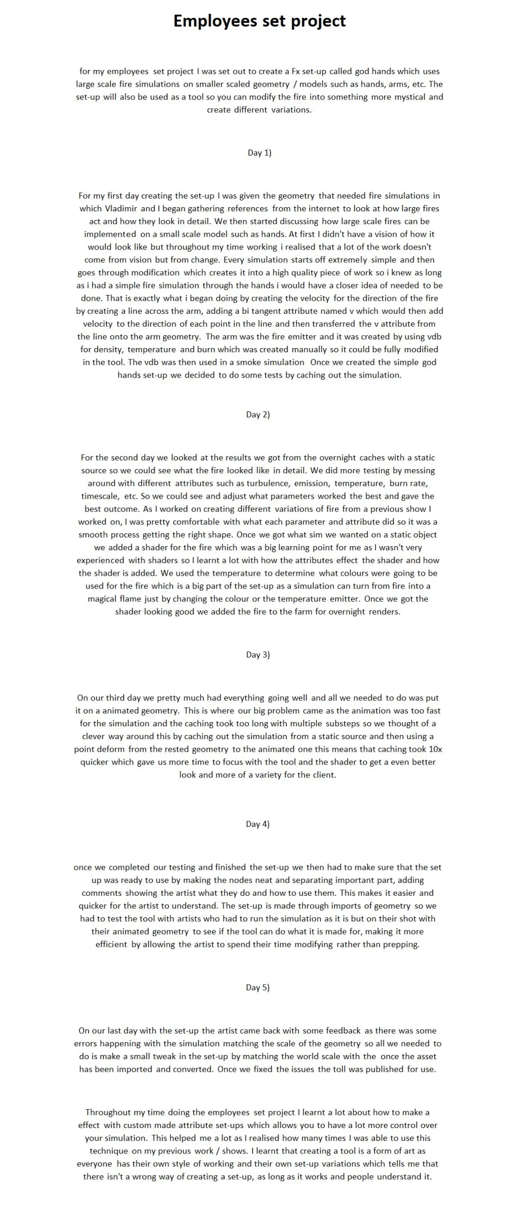